Programmable LED Lava Lamp

FadeCandy is a Neopixel driver that excels in creating LED art with it's built in dithering that can be controlled via USB. The dithering gives LEDs a smoother in between color rather than the hard transitions from other LEDS. In fact, FadeCandy works with the popular WS2812B LEDs as well as others from third parties. Each FadeCandy board can power up to 512 LEDs, that's 64 LEDs on each of the 8 channels. The board supports many different languages such as Processing, Python, and C just to name a few. It also communicates to the LEDs on the computer via server protocol.
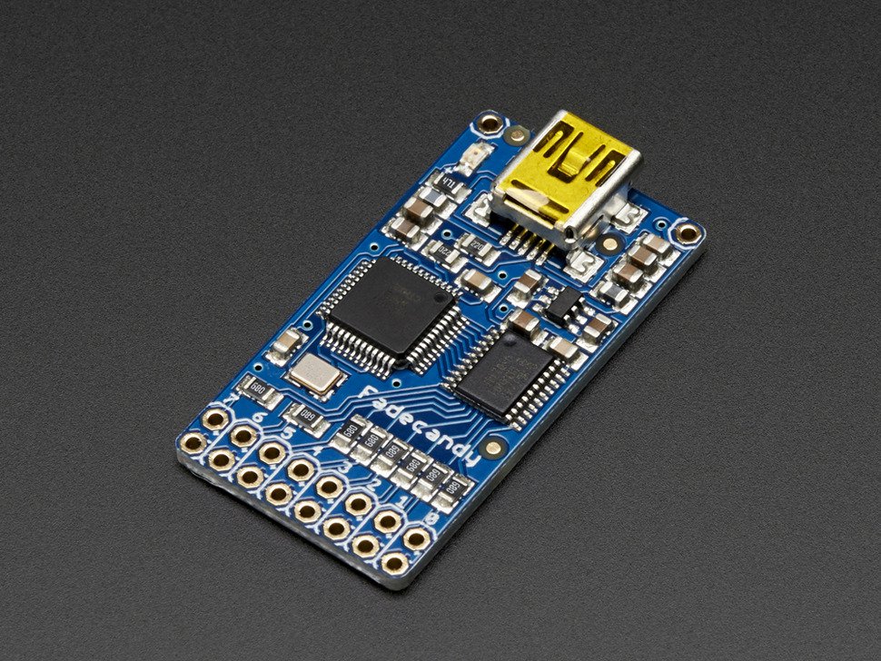
FadeCandy board
Power Setup and Wiring
Power consumption on LED projects can vary greatly and having the right power supply is crucial. I wanted a good height to the LED lamp so I decided that 8 strips of 15 LEDs was sufficient. That's a total of 120 LEDs to power. The FadeCandy has 8 total channels that can drive up to 64 LEDs each. Therefore I connected 120 LEDs split over two channels.
Next was determining how much power the lamp would consume. At full brightness, a single LED pixel draws about 60 mA at 5V. My LED lamp would consume 7.2A on full brightness (120 LEDs x 60 mA). Although my lamp would never have all LEDs operate on full brightness at once, I conservatively chose a 10A 5V power supply. I also choose to use 18 gauge (AWG) wire because they were rated for 16A which was more than enough to prevent overheating. I wanted the LED strips to be easily disassembled so I chose to create my own JST connectors then solder the wires onto the LED strips.
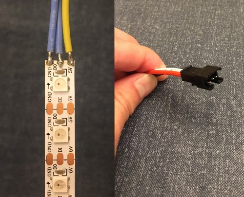
Cut the LED strips into desired lengths then soldered the wires with JST connectors onto the strips.
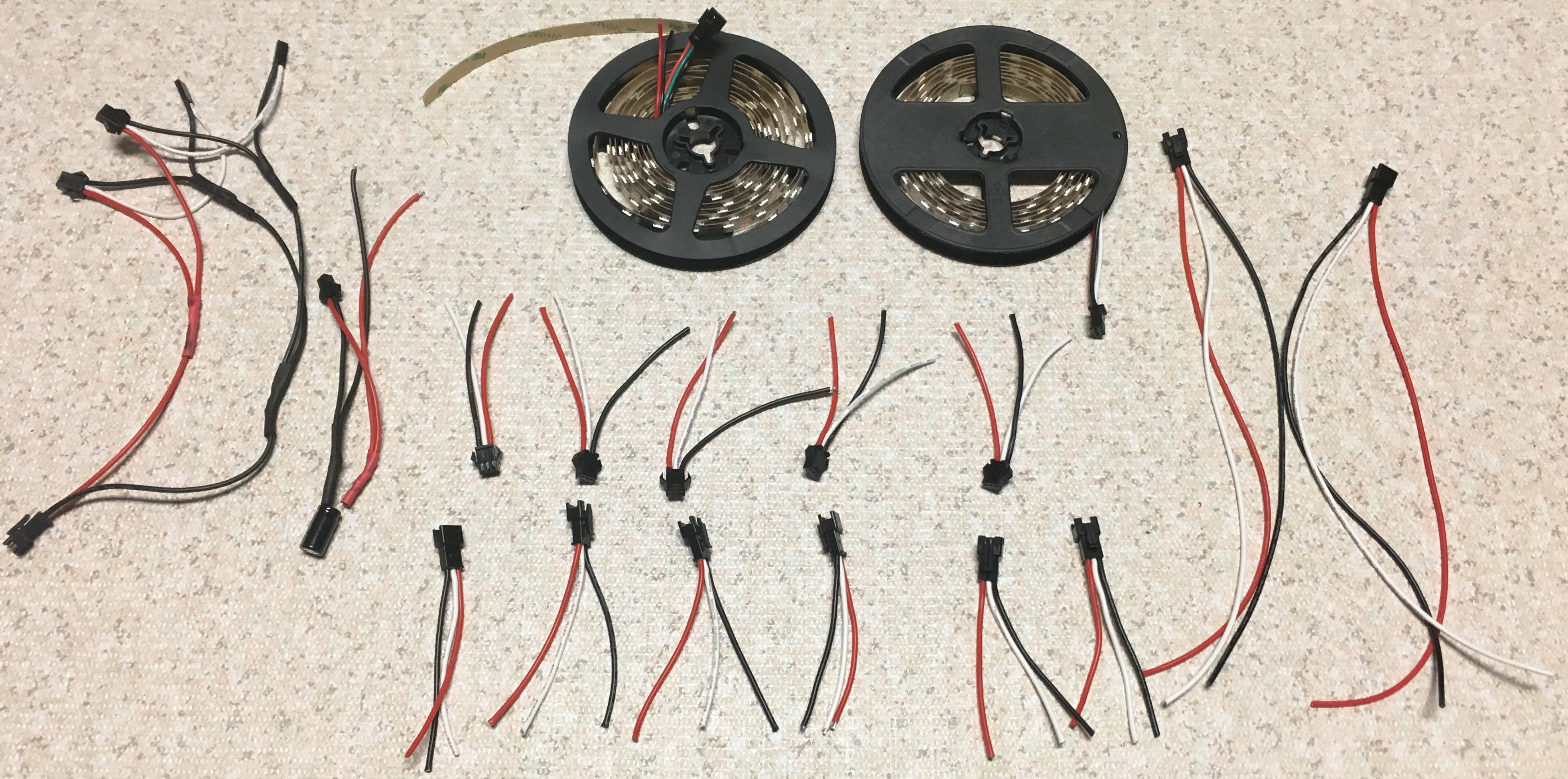
Here are all the necessary wires and the JST connectors I made that were eventually soldered onto the LED strips. I decided to add a 1000 microfard 6.3V capacitor to the power supply to prevent the initial rush of current from damaging the pixels as well.
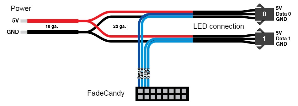
An overview of how everything in this project connects together. Since I am powering two sets of LED strips, both the 5V and GND need to connect to them. We can do this by creating a three way inline splice which takes a single power wire and splits into two. This same thing is created for the GND wires as well. On the right are the JST connections to the LED strips. The Data and GND from the LED strips are then connected to the FadeCandy controller. Another three way inline splice was created to link the LED strip and FadeCandy grounds together with the main ground.
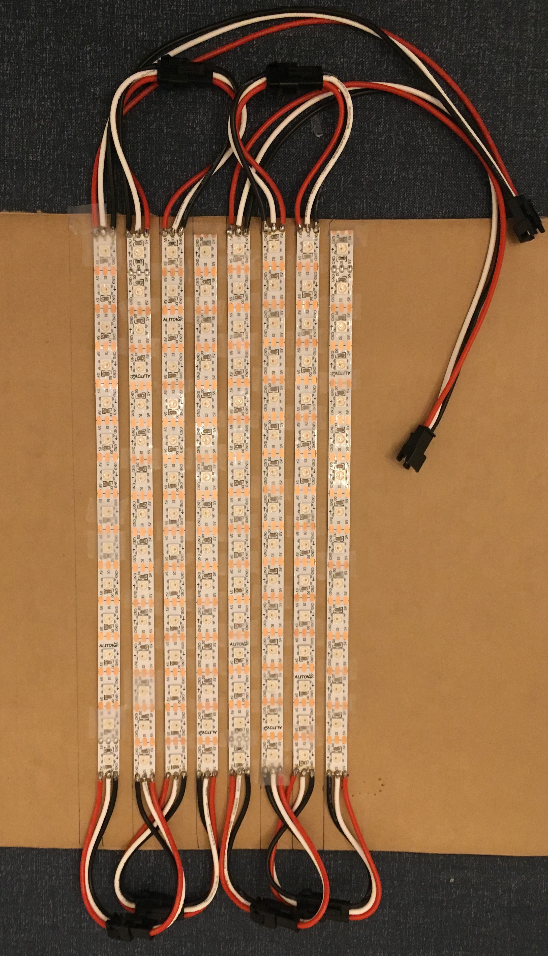
Once the LED strips had all their JST connectors soldered on, I arranged them in a 8x15 grid connected in a zigzag pattern on a flat surface first. This allowed me to test my wire connections and LEDs with the FadeCandy.
Testing and Assembly
The FadeCandy runs on the Processing programming language which is ideal for creating multimedia art. After installing the Processing IDE I tested my grid using some of their examples. There were some modifications to their code such as changing the grid layout to 8x15 and re-orientating.
I wrapped the LED grid around 1 1/4 in PVC pipe using adhesives and 3D printed a base for the PVC pipe to attach to.
I found a vase at a local crafts store to cover the LEDs.
LED testing

To diffuse the light on the lamp, I decided to go with sheets of mylar. These mylar sheets were intended for stencil making because of their transparency but they worked well as a diffuser. It took about 6 sheets of mylar to diffuse the light where you could no longer make out the LEDs.

3D printed the base which the electronics will go inside of (left), the lid holds the PVC pipe and the vase (right)
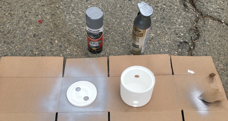
Post processed the printed parts, sanding them first followed by primer and multiple coats of paint

Wanted to give the part a metal look for nicer aesthetic
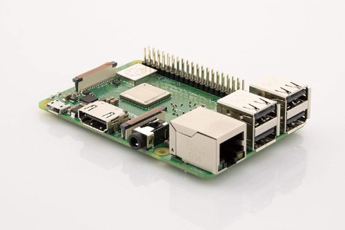
Operating the Fadecandy controller requires a computer to connect to a server. Since I wanted this lamp to be standalone, I added a Raspberry Pi for the server to run on. I also added a startup sketch that ran upon booting the Raspberry Pi.

Added two normally open momentary push buttons, one to power on the Raspberry Pi (left), the other to enable switching lamp modes (right). When the button is pressed, a GPIO event is triggered to cycle through the sketch array (different light modes).
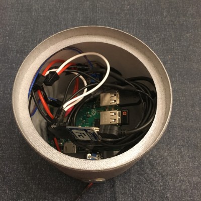
All of the wiring and boards placed inside the base

LED lamp assembled
Different modes for LED lamp